A pressure sensing element alone does not provide a complete pressure measurement solution. To deliver a usable and stable output signal, the sensing element must be integrated with appropriate mechanical structures, electronic circuits, calibration functions, and electrical interfaces.
Pressure sensor module integration is therefore an important part of developing reliable pressure measurement products for automotive, industrial, hydraulic, pneumatic, and fluid control applications.
For OEM manufacturers, a well-designed pressure sensor module can simplify system integration, reduce additional electronic development work, and provide a more consistent interface with the host equipment.
This article explains the main stages of pressure sensor module integration and the technical factors engineers should evaluate during product development.
1. What Is Pressure Sensor Module Integration?
Pressure sensor module integration refers to combining the sensing element with the necessary electronic and mechanical components to create a functional pressure measurement assembly.
Depending on the product architecture, a module may include:
-
A pressure sensing element
-
Electrical excitation and signal conditioning
-
Amplification and signal conversion
-
-
Calibration data or correction functions
-
Electrical output connections
-
Mechanical support and protection
Not every pressure module contains all these components.
Some modules provide a raw sensing signal for integration into a customer’s control board, while others provide a conditioned analog or digital output.
Therefore, the module interface and integration boundary should be clearly defined before OEM development begins.
2. Main Architecture of a Pressure Sensor Module
A typical integrated pressure measurement architecture can be divided into several functional stages.
The sensing element detects pressure and generates a corresponding electrical change.
Common technologies include:
-
Ceramic piezoresistive sensing
-
Ceramic capacitive sensing
-
Silicon piezoresistive sensing
The appropriate sensing technology depends on the pressure range, measurement medium, operating temperature, required sensitivity, and mechanical design.
2.2 Signal Conditioning Circuit
The electrical signal generated by a sensing element may require amplification, filtering, linearization, and compensation.
For example, a piezoresistive bridge produces a relatively small differential electrical signal. Signal-conditioning electronics can amplify and process this signal before it is delivered to the output interface.
2.3 Analog-to-Digital Conversion
Some pressure modules use an analog-to-digital converter (ADC) to transform the conditioned sensing signal into digital data.
The digital value can then be processed by an application-specific integrated circuit (ASIC) or microcontroller.
The exact architecture depends on the sensing principle, accuracy requirements, output interface, and power budget.
2.4 Output Interface
The final stage delivers pressure information to the connected controller or measurement system.
Common output configurations include voltage, current, and digital interfaces.
The output must be compatible with the electrical requirements of the target equipment.
Output selection is one of the most important decisions during module integration.
| Output Type |
Typical Application Considerations |
| Raw bridge signal |
External amplification and signal processing required |
| Voltage output |
Direct connection to compatible analog input circuits |
| Ratiometric voltage |
Useful when the receiving ADC reference tracks the sensor supply |
| 4–20 mA output |
Common in industrial control and process measurement |
| Digital output |
Requires a compatible communication protocol |
Voltage Output
Voltage output provides an electrical signal corresponding to the measured pressure.
Before selecting a voltage-output module, engineers should confirm the output range, supply voltage, input impedance, and allowable electrical load.
Ratiometric Output
A ratiometric sensor output changes in proportion to its supply voltage.
When the receiving ADC uses the same supply reference, the ratio between the measured output and reference can help reduce errors caused by supply-voltage variations.
However, this benefit depends on the actual circuit architecture and wiring arrangement. Supply and reference compatibility must be verified during integration.
Current Output
A 4–20 mA output is commonly used in industrial measurement and control systems.
The design must consider loop supply voltage, total circuit resistance, wiring conditions, and the available voltage margin.
Digital Output
Digital interfaces can reduce the need for additional analog signal-processing circuits in the host equipment.
Depending on the module design, interfaces may include SPI, UART, or other supported protocols.
Communication speed, voltage levels, data format, error detection, and startup behavior should all be defined before implementation.
4. Why Temperature Compensation Matters
Temperature changes can affect both the sensing element and its associated electronics.
Without appropriate compensation, the measured pressure signal may shift as the operating temperature changes.
Two important parameters are:
Zero-point temperature drift: Changes in the output when the applied pressure remains at its reference point.
Span temperature drift: Changes in measurement sensitivity across the pressure range.
A pressure sensor module may use hardware compensation, software correction, or a combination of both.
Digital compensation typically involves measuring the sensor response at selected temperature and pressure points, calculating correction coefficients, and applying these coefficients during signal processing.
The required calibration points and correction method depend on the target operating range and accuracy requirements.
5. Pressure Sensor Module Calibration
Calibration helps establish the relationship between applied pressure and the module’s output signal.
A controlled calibration process should consider several factors.
Pressure Reference
Use an appropriate pressure reference with suitable accuracy and measurement uncertainty for the required specification.
Multi-Point Calibration
Rather than checking only zero and full-scale pressure, multiple pressure points can help identify nonlinearity across the measurement range.
Temperature Calibration
Where wide temperature operation is required, evaluate zero and span behavior at relevant temperature points.
Repeatability and Hysteresis
Apply increasing and decreasing pressure sequences to evaluate whether the output returns consistently under repeated conditions.
Calibration Data Management
For electronically compensated designs, document calibration coefficients, software or firmware versions, test conditions, and acceptance criteria.
This helps maintain traceability throughout product development and manufacturing.
6. PCB Design and Electrical Protection
The quality of the electronic integration can significantly influence measurement stability.
Several design practices should be considered:
-
Keep sensitive analog signal paths short.
-
Separate low-level sensing signals from high-frequency switching circuits.
-
Use suitable grounding and return-current paths.
-
Place power-supply decoupling components close to the relevant IC pins.
-
Evaluate electromagnetic interference and electrostatic discharge protection.
-
Check connector pin assignments and cable characteristics.
-
Consider reverse-polarity and overvoltage protection where required.
Protection components must be selected according to the actual electrical environment. Excessive filtering or unsuitable circuit protection can also affect measurement response.
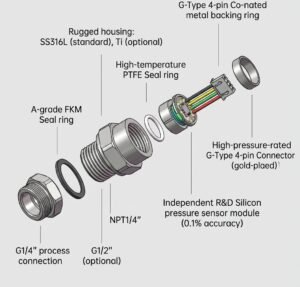
7. Mechanical Integration and Environmental Requirements
Electrical design alone cannot guarantee a reliable pressure measurement assembly.
The mechanical structure must be compatible with the application.
Pressure Connection
Confirm thread type, sealing method, installation dimensions, and mounting torque.
Media Compatibility
Evaluate every wetted material, including the diaphragm, pressure port, seals, and other exposed components.
Vibration and Pressure Pulsation
Automotive and industrial equipment may experience vibration, shock, and dynamic pressure changes.
The sensing structure and mechanical housing should be evaluated under realistic operating conditions.
Temperature and Environmental Protection
Consider temperature cycling, humidity, water exposure, contamination, and the location of the module within the equipment.
For automotive electronic components, ISO 16750 provides a framework for evaluating environmental conditions and tests, including electrical, mechanical, climatic, and chemical loads in its respective parts.
The applicable requirements should be selected according to the installation location and OEM specifications. ISO 16750-2, for example, addresses electrical loads, not EMC testing itself.
8. OEM Customization Considerations
Different equipment manufacturers may have different pressure measurement requirements.
A practical OEM specification should define the following information before module development:
| Design Parameter |
Information to Confirm |
| Pressure range |
Minimum, nominal, and maximum pressure |
| Measurement type |
Gauge, absolute, or sealed gauge |
| Sensing technology |
Ceramic piezoresistive, capacitive, or other |
| Output |
Voltage, current, or digital |
| Supply |
Nominal voltage and allowable variation |
| Accuracy |
Required total measurement accuracy |
| Temperature |
Operating and storage temperatures |
| Media |
Gas, liquid, oil, coolant, or refrigerant |
| Mechanical interface |
Dimensions, mounting, and pressure port |
| Electrical interface |
Connector, pinout, and cable |
| Environment |
Vibration, shock, humidity, and EMC requirements |
Defining these requirements early can reduce unnecessary design changes and help the supplier evaluate the feasibility of the proposed solution.
Pressure sensor module integration involves more than connecting a sensing element to an electronic circuit.
The sensing technology, signal conditioning, temperature compensation, calibration, mechanical design, and electrical interface must work together to achieve the required measurement performance.
For automotive and industrial OEM applications, clearly defining the system requirements before module selection or customization is an important step toward reliable integration.
Looking for a pressure sensor module for your OEM project?
OULD provides pressure sensing products, ceramic sensing elements, and pressure transmitter module solutions for different industrial measurement applications.
Contact our team to discuss your required pressure range, signal output, installation dimensions, and customization requirements.